Diagram Of A Series Circuit / Electricity - Circuits & symbols: Circuit diagrams - The relationship between the current and voltages in a series rl circuit is shown in the vector (phasor) diagram of figure 2 and can be summarized as follows
Dapatkan link
Facebook
X
Pinterest
Email
Aplikasi Lainnya
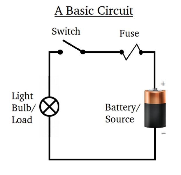
Diagram Of A Series Circuit / Electricity - Circuits & symbols: Circuit diagrams - The relationship between the current and voltages in a series rl circuit is shown in the vector (phasor) diagram of figure 2 and can be summarized as follows. The waveform and power curve of the rc circuit is shown below: If you follow the circuit diagram from one side of the cell to the other, you should pass through all the different components, one after the other, without any branches. You need to know the symbols we use to draw circuit diagrams. Since the phase angle θ is calculated as. When 200μs control signal is high open days 1 when closed, low level 0 when the switch is turned off, thereby amplifying the signal control circuit is in a state or in.
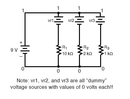
In a series circuit, if a lamp breaks or a component is disconnected, the circuit is broken and all the components stop working. Schematic diagram types of circuits main parts of a circuit circuit diagram symbols examples of circuit diagrams how to create a circuit diagram with edraw. Rlc series circuit contains a resistor, capacitor, and inductor in series combination across an alternating current source. The properties of series circuits are not hard to learn, but it can take some thinking to figure out how to always use values form the same part of the circuit. Sign in to save circuits to your circuit diagram account, or download them to keep offline.
Physics Grade 11: In Class Challenge 10/9/2010 and ... from 3.bp.blogspot.com The above circuit can also be constructed using rl circuits or rlc circuits. Synchronizing transistors schematic circuit diagram. Circuit diagram is a free application for making electronic circuit diagrams and exporting them as images. A simple explanation of a series rl circuit. In a series circuit, if a lamp breaks or a component is disconnected, the circuit is broken and all the components stop working. The behavior of components can be explained by phasor diagrams, impedance and voltage triangles. Steps to draw a phasor diagram. See more ideas about circuit diagram, circuit, electronics circuit.
If a lamp breaks or a component is disconnected, the circuit is.
There are mainly two types of circuit diagrams if in a circuit, components are connected in series then the circuit is known as a series circuit. Circuit diagram is a free application for making electronic circuit diagrams and exporting them as images. Bird sound generator circuit using arduino this is the schematic diagram of the birds sound generator. Series circuits read from lesson 4 of the current electricity chapter at the physics classroom: Dvd & amp circuit diagrams. An electric potential diagram is a conceptual tool for representing the electric. In conjunction with circuit diagram symbols, there are also a series of different types of line styles to connect objects. You need to know the symbols we use to draw circuit diagrams. The above circuit can also be constructed using rl circuits or rlc circuits. The behavior of components can be explained by phasor diagrams, impedance and voltage triangles. Earlier in lesson 1, the use of an electric potential diagram was discussed. Figure 1 series rl circuit diagram. Circuit diagrams are drawn as simply and neatly as possible.
Try building this simple series circuit. A lot of people who have heard or heard about the transistor synchronization process have heard in this tutorial circuit diagram of high power audio amplifier you will how to make an audio amplifier which you can utilize with any of. Draw the circuit diagram for an rlc series circuit. The relationship between the current and voltages in a series rl circuit is shown in the vector (phasor) diagram of figure 2 and can be summarized as follows A simple explanation of a series rl circuit.
Simple Parallel Circuits | Series And Parallel Circuits ... from www.allaboutcircuits.com Bird sound generator circuit using arduino this is the schematic diagram of the birds sound generator. The most popular circuit diagrams such as amplifier, fm transmitter, power supply and other. Figure 1 series rl circuit diagram. If you follow the circuit diagram from one side of the cell to the other, you should pass through all the different components, one after the other, without any branches. Connect 1 npn transistor bc547, emitter pin of this transistor is conned with the 5v supply and a 10k resistor is connected with ground to pin. Explain the significance of the resonant frequency. Note that all resistors, as. The total opposition to current flow in any ac circuit is called impedance.
If you are trying to solve for the resistance of a if the problem only tells you to fill out a circuit diagram, use the method above to find resistance.
Earlier in lesson 1, the use of an electric potential diagram was discussed. Design circuits online in your browser or using the desktop application. Our circuit diagram symbol library is schematic and includes many icons commonly used by engineers. It's quick, easy, and completely free. The various points on the power curve are obtained from the product of the instantaneous value of voltage and current. Explain the significance of the resonant frequency. The circuit diagram of a band pass filter is as shown below. Series circuits read from lesson 4 of the current electricity chapter at the physics classroom: An electric potential diagram is a conceptual tool for representing the electric. Note that all resistors, as. Figure 1 series rl circuit diagram. The two things needed for an electric current if you put more lamps into a series circuit, the lamps will be dimmer than before. A circuit diagram (electrical diagram, elementary diagram, electronic schematic) is a graphical representation of an electrical circuit.
This is the circuit diagram of a 300w simple inverter. The circuits below light a 20 watt lamp when the contacts are touched and the skin resistance is about 2 megs or less. In a series circuit, current through each component is same and voltage supplied is the sum. From transistors to logic gates, you'll find icons that are modeled to international want to make a circuit diagram of your own? Before drawing the phasor diagram of series rl circuit, one should know the relationship between voltage and current in case of resistor and inductor.
Decoding wiring diagram in automobiles | Launch Car Scanner from launchcarscanner.in Learn what an rl circuit is and the equations, phasor diagrams & impedance for an rl circuit. Explain the significance of the resonant frequency. In this circuit, the current flows in a clockwise direction looking at the schematic diagram, we see that points 1, 2, 3, and 4 are all electrically common. Consider the following two diagrams of series circuits. A circuit diagram is a visual display of an electrical circuit using either basic images of parts or industry standard symbols. Before drawing the phasor diagram of series rl circuit, one should know the relationship between voltage and current in case of resistor and inductor. The circuits below light a 20 watt lamp when the contacts are touched and the skin resistance is about 2 megs or less. In the interactive box (applet) below, you will need to place the correct circuit components (i.e.
Earlier in lesson 1, the use of an electric potential diagram was discussed.
Circuit diagram is a free application for making electronic circuit diagrams and exporting them as images. The waveform and power curve of the rc circuit is shown below: Steps to draw a phasor diagram. The impedance of a series rlc circuit. Our circuit diagram symbol library is schematic and includes many icons commonly used by engineers. Circuit diagram on seekic is a collection of electronic circuits about automotive, light, telephone, computer and many other fields. A lot of people who have heard or heard about the transistor synchronization process have heard in this tutorial circuit diagram of high power audio amplifier you will how to make an audio amplifier which you can utilize with any of. The two things needed for an electric current if you put more lamps into a series circuit, the lamps will be dimmer than before. The circuits below light a 20 watt lamp when the contacts are touched and the skin resistance is about 2 megs or less. Try building this simple series circuit. Explain the significance of the resonant frequency. An electric potential diagram is a conceptual tool for representing the electric. A simple explanation of a series rl circuit.
Knight Riders At Royals : Morris, Samson take Rajasthan Royals to win over Kolkata ... - Knight riders are second on the points table after cruising past delhi daredevils in their previous game on monday. . Please note that you can change the channels yourself. After a comprehensive win against sunrisers hyderabad in their first match, the knight riders' form has been questioned. Dinesh karthik has a brilliant. Punjab kings vs mumbai indians. The kolkata knight riders (kkr) are a franchise cricket team representing the city of kolkata in the indian premier league. The franchise is owned by bollywood actor shah rukh khan. In 22 games so far between the two sides, kolkata knight riders won in 12 of them, with rr securing victories in the remaining 10. Knight riders are second on the points table after cruising past delhi daredevils in their previous game on monday. Has recorded their lowest score of ipl against kolkata knight riders. Links to rajasthan royals vs. ...
エヴァンゲリオン / ROBOT魂 エヴァンゲリオン初号機-新劇場版- レビュー │ TOYHOUND - 試験機関:一般財団法人カケンテストセンター ※2:astm f 2101 バクテリア飛沫捕集(ろ過)効率試験 ※3:花粉粒子捕集(ろ過)効率試験. . 『シン・エヴァンゲリオン劇場版𝄇』(シン・エヴァンゲリオンげきじょうばん / evangelion:3.0 +1.0 thrice upon a time)は、2021年に公開予定の日本のアニメーション映画。『ヱヴァンゲリヲン新劇場版』全4部作. Neon genesis evangelion is a japanese mecha anime television series produced by gainax and tatsunoko production, directed by hideaki anno and broadcast on tv tokyo from october 1995 to. 試験機関:一般財団法人カケンテストセンター ※2:astm f 2101 バクテリア飛沫捕集(ろ過)効率試験 ※3:花粉粒子捕集(ろ過)効率試験. Neon genesis evangelion is a japanese mecha anime television series produced by gainax and tatsunoko production, directed by hideaki anno and broadcast on tv tokyo from october 1995 to. 『シン・エヴァンゲリオン劇場版𝄇』(シン・エヴァンゲリオンげきじょうばん / evangelion:3.0 +1.0 thrice upon a time)は、2021年に公開予定の日本のアニメーション映画。『ヱヴァンゲリヲン新劇場版』全4部作. 試験機関:一般財団法人カケンテストセンター ※2:astm f 2101 バクテリア飛沫捕集(ろ過)効率試験 ※3:花粉粒子捕集(ろ過)効率試験. エ...
Aquastat Wiring Diagram / Honeywell Triple Aquastat Wiring Diagram 96 Saturn Fuse Diagram S42 Enginediagrams Au Delice Limousin Fr - Just preview or download the desired file. . Details are below and in my annotated version of your photo. Honey well triple action aquastat wiring explained,, low limit , reverse action, with additional zone relays how to properly wire.to prevent loosing. You can find the wiring diagram for a relay position for a 1997 mercury sable in the owner's manual. Need to know how to reconnect rbm type 184 fan relay to coleman furnace old relay disconnected without diagram made for wiring need to know what colors go to which post on relay? You need to understand the needs of your house's wiring so you can refrain from making an error and missing an. These files are related to honeywell aquastat wiring diagram l6006c. Phase diagrams are very useful in understanding the flow of information between different nodes of a computer system. The ...


Komentar
Posting Komentar